Wednesday, April 17, 2019

Wiring Methods and Swimming Pools - So What Is A Corrosive Environment?

With the 2020 National Electrical Code updates right around the corner and the dust finally settling on the code panel meetings in San Diego, CA we code users begin to reflect on a few of the changes that are taking place with wiring methods used in swimming pool environments. This article will attempt to shed some light on those developments. For a few code cycles now the code user (and code developers) have struggled with the term "corrosive environment" and how it applies to the swimming pool environment. We all collectively understand that the "condition of use" in those environments, such as pool rooms and locations where pool treatment chemicals are stored and of course the pool pump equipment is located do have an elevated potential for being a higher than normal environment where corrosion can take place. However, once we begin to look at these environments and the existing wiring methods permitted within them do we begin to question why no standards exist to provide a detailed evaluation of the environment. Let me go into that in more detail. Let us paint the scenario for the reader so as to better illustrate the "condition of use" involved. We have a single-family dwelling with a swimming pool and associated pump and recirculation equipment, chlorine or bromine tablet or liquids and, where applicable, their injectors as well as the storage containers for those chemicals. Based on the 2020 NEC that location would be considered a "corrosive environment" based on the proposed language :
No alt text provided for this image
This is a considerable change to the definition found in the 2017 NEC under section 680.14(A). In fact, it still remains unclear as to what exactly constitutes such a "corrosive environment" based on the concentrations of such chemicals unlike how we clearly define "combustible dust" in Article 100. We can all agree the environment does warrant an elevated consideration similar to those of exterior locations where the same existing wiring methods are currently used, except of course for the chemicals in the pool sanitation process. Traditionally the NEC has permitted Rigid Metal Conduit (RMC), Intermediate Metal Conduit (IMC), Polyvinyl Chloride Conduit (PVC) and Reinforced Thermosetting Resin Conduit (RTTC) in these locations without any formal investigation to their suitability for the "condition of use" that the code- making- panels seems to believe is a highly corrosive environment. But let's not stop there and actually look at the "other" electrical equipment permitted to be installed in these areas without any concern about their suitability. These pool rooms typically contain electrical pool distribution panels with plastic circuit breakers, which are terminated onto exposed bus assemblies with exposed conductor terminations. The luminaries typically found in these rooms are not rated for a "corrosive environment" as expressed in the definition found in Article 680. Let's not forget to mention that the majority of the pool equipment is PVC that does come in indirect or direct contact with the chemicals being used. And it only serves as a good reminder that none of the actual wiring methods expressed in 680.14(B) for the 2017 NEC or the proposed 680.14 in the 2020 NEC have actually been evaluated for those environments as well because no standard exists to cover the swimming pools "corrosive environment" area and the leading NRTL's are aware of it. While we are on the topic of wiring methods, and of course that was the title of this article, lets examine the current NEC proposed language for the wiring methods permitted in a "Corrosive Environment".
No alt text provided for this image
As you see above the language has changed or is proposed to change. The rule opens with the following statement: "Wiring methods in a corrosive environment" shall be listed and identified for use in such areas." and ends with the list of existing wiring methods that have technically been "grandfathered" into the rule. The reason I say "grandfathered" is because none of the wiring methods in the list have been evaluated for the harsh condition that the CMP believes exists. However, let's focus on a wiring method that is excluded from that list that has proven it's merit in those harsh environments for years. During the 2017 NEC development process as well as in the current 2020 development process of the NEC it was presented that PVC Jacketed or Covered Type MC (Metal-clad) Cable should be included in that list. Let's examine the facts from the position of the National Electrical Code, the electrical industries minimal safety standard as well as the actual product standard, UL 1569. 1) UL 1569 states in section 13.2 that "steel" armor must have corrosive resistant zinc applied to the strip much in the same fashion as with RMC and IMC. So while the aluminum version doesn't have the same protection you will see later that the PVC Jacketing or Covering will provide that protection. 2) Section 330.10(A)(11) of the 2017 NEC states "In wet locations where a corrosion resistant jacket is provided over the metallic covering and any of the following conditions are met." The most often used method used to comply with this rule is by using insulated interior conductors that are listed for use in wet locations, such as THHN/THWN-2 or XHHW-2. In fact, it was argued during the 2017 NEC NITMAM stage that both indoor or outdoor wet locations can be considered a corrosive environment. So clearly the entire intent of the PVC Jacketing or Covering over the metal armor meets this intent. 3) Section 330.12, which is the "uses not permitted" section of this article clearly prohibits the use of Type MC in locations where it is subject to physical damage or destructive corrosive environments. However, it does permit that Type MC is acceptable in these environments if protected by material resistant to the condition. This is where the PVC Jacketed or Covered come into play. Remember, there is no related UL/ANSI Standard for the harsh pool environment to test against. 4) Back to that UL 1569 Standard for a second. It has been stated for years by some folks very close, if not intimate with that standard, that UL 1569 already permits Type MC Cable with a PVC Jacketed or Covering to be used for connections to swimming pool motors in those same "conditions of use" without any problems. In fact, some folks even argue that some "special" testing takes place in UL 1569 that demands that manufacture place the wording "Suitable for use in swimming pool motor circuits" on PVC Jacketed or Covered Type MC when used for swimming pool motors. However, a close examination of section 40.1(o) in UL 1569, it states that manufacturers who produce such a cable assembly "may" mark the cable assembly "may be marked" with that statement but doesn't require it and clearly nothing in that standard or any other standard demands any additional testing to take place. Wait, is the standards telling me PVC Jacketed or Covered Type MC Cable is ok for use with pool pump motors as permitted in 680.21(A)(1) of the NEC for decades without any concerns? In light of the information above those who are aggressively against the use of Type MC with a PVC Jacketing or Covering then turned to the connectors as their target for the weakness. We reached out to one of the leading manufacturers of connectors to address this question and they stated while there is no formal testing for this specific "pool environment", they feel that the existing connectors rated for wet locations would be sufficient for this application. When that effort was squashed they then turned to the armor and said it provided a Grounding Path and the potential corrosion to that armor could be detrimental to that path which was ultimately explained to that member that normal PVC Jacketed or Covered Type MC Cable armor is not considered such a path but is bonded by virtue of the fittings to meet the bonding requirements. Also, they were reminded that Rigid Metal Conduit (RMC) is in fact permitted to serve as the Equipment Grounding Conductor (EGC) by section 250.118(2) and are routinely found damaged and that traditional Type MC Cable has an internal EGC to ensure that connection remains reliable. In an effort to clarify the durability of the PVC material used on Type MC this author reached out to individuals at IPEX, leaders in the non-metallic pipe and fitting industry since 1951. IPEX also publishes an industry-leading guide called the "IPEX Chemical Resistance Guide" used to determine the various factors in the chemical attack onto PVC material along with may other materials. It was made clear to this author that the chlorine used in pools is actually chlorine water with an approximate concentration of chlorine of 10-13%. This is a far cry from pure chlorine liquid, which would destroy any of the permitted wiring methods currently allowed. The chart provided documented proof that PVC is resistant to the attack of chlorine water and of course since 90% of the pool pumps, recirculation systems and storage containers are PVC themselves this would make total sense. They also went on to explain that PVC material in the presence of Boric Acid, Bromine-AG , and Hydrochloric Acid also has no negative affect on the PVC material. In an effort to get to the bottom of this PVC issue once and for all (wrong) Encore Wire set up a controlled test in our DAP Certified UL Lab to study the effects of long term exposure (12 months) of Type MC , both PVC Jacketed or Covered Aluminum and Steel Armor products in a harsh chemical environment. The worst case scenario was to use hydrochloric acid vapor in its purest form knowing the vapor would envelope the samples and with the normal Texas heat, create condensed liquid from that vapor that would be deposited on the samples over the test period. The samples also included both standard Type MC in their aluminum and steel forms. Long story short, the aforementioned results were presented in full detail to CMP 17 and provided undeniable proof that even after 12 months of exposure in our environment here in Texas where temperatures reached over 100 degrees on a regular basis, that no negative effects appeared on any of the samples with the PVC Jacketed or Covered Type MC Cable. Lastly, let's examine the 2020 NEC proposed language for section 680.14 and what I believe permits (my opinion) the use of PVC Jacketed or Covered Type MC Cable.
No alt text provided for this image
Clearly, Type MC Cable is listed and when it is PVC Jacketed or Covered it is also evaluated for direct burial applications in locations we have determined are also corrosive environments or otherwise why put a jacket or covering on it in the first place. The allowances, or should I say permission is given in the previously discussed section 330.10(11) and 330.12(2) for the use in those such environments covers that opening sentences permission to use PVC Jacketed or Covered Type MC Cable. It is also my personal opinion that the new language proposed in section 680.2 only describes the locations to be considered a "corrosive environment" and adds nothing to define it. Under additional analysis, the second sentence simply offers "grandfathered" recommendations of those untested wiring methods to be considered acceptable wiring methods that have again yet to be evaluated for the "condition of use" described by CMP 17 as a "Corrosive Environment". Conclusion - There is no doubt that these environments can increase the potential for a corrosive environment. However, it has been proven with test data and the leading chemical resistance guides that the PVC Material placed on cables or raceways can provide an adequate protection against a corrosive environment. In fact, it could be argued that Type MC Cable with a PVC Jacket or Covering is the only wiring method with adequate testings for these specific "conditions of use".
Paul W Abernathy, CMECP®
Notice : NEC® and National Electrical Code® are registered trademarks of the National Fire Protection Association and are used for educational purposes only. All "NEC®" inserts are used for clarity and educational purposes and are not altered from their original format as expressed in the NFPA 2nd Draft Public Comment Stage.

Tuesday, January 15, 2019

The Stagnant Mind - Pull Box Calculations and Closed Minds Collide

One of the most rewarding feeling in life, as a future tradesman, is when you study real hard, stay up late for months reading countless books on the National Electrical Code®. Heck, you may even binge watch endless youtube videos to prepare for an upcoming electrical exam and start to really understand the code, you're rightfully pumping with pride. Then it happens, you visit the water cooler at work and ask a code question to an experienced electrician who you consider knowledgeable and your world comes crashing down on you. Was all that learning wasted?
This article is written to show a classic response when using an industry trade "facebook-type" forum. An illustration, similar to the one shown below, was introduced to the group of presumably licensed and well qualified electricians for comment. The responses and harassment this author received would frankly shock you. From "It can't be solved" to "What a terrible question" and many more that are too graphic in nature to present in this article. In fact, the illustration depicted in the exercise was from one of the leading electrical educators in the country and very commonly seen on electrical exams all across the country, as stated by the author of the published illustration. So I created the illustrations below for a technically exhaustive look at how to solve this common exam illustration.
When a student is preparing for an exam, good instructors take them through phases of learning where they have to solve for what they see based on the information provided because there is a distinct difference from an exam based question and real world question. The illustration provides raceways entries into a pull box from all available sides. The conductors are 4 AWG and Larger and plausibly can be routed in straight or angle directions so the students must adapt and account for that plausibility. However, as commonly seen on electrical exams we are not showing the actual conductors, how they may be routed, or what size they are for this basic exercise. Why? Because typically a basic electrical exam will not have questions that incorporate many possibly outcomes.
So accordingly, the student will look at the pull box and quickly observe only the information presented. A pull box with raceway entries on all sides, the student will ask themselves, what and how would I calculate the minimum NEC® compliant pull box dimensions based on what is presented? Here is where it gets interesting.
One user on Facebooks "Electricians Only" type forums stated " Impossible to answer without knowing if there are angle or straight pulls and which raceways those pulls are coming out of..". This is where we began to examine those statements from a student learning the NEC® perspective as opposed to an experienced yet be it closed minded approach from those well rooted in the trade for many years.
Upon examination, we have raceway entries on all available sides of this illustrated pull box. It is critical to remember that students taking an electrical exam, be it PSI or other nationally accepted licensing exam, have to ignore the "Real World" and simply answer the question as presented. The student has to endeavor to solve for the minimum size pull box based solely on the information provided utilizing sections 314.28(A)(1) and (A)(2) of the National Electrical Code®.
Since no conductor sizes exist, other than the 4 AWG and larger demanded by 314.28(A), the student would look at this illustration and utilize a common sense approach by assuming both Straight Pulls and Angle Pulls are plausible. In this exam only, purely fictional installation attempt to solve for "X" and "Y" as requested. Remember, the student is asked to solve for dimensions "X" and "Y" only and no other dimension.
Interesting Fact- There are other dimensions that can play a role, such as for "Z" where raceways enclosing the same conductor are used distances between those raceways have to be accounted for, that is for later in this article since only "X" and "Y" are originally requested.
LETS BEGIN THE MATH
  • Left Side X Value - Section 314.28(A)(1) states that the length of the box shall not be less than eight times the trade size (we will use inches in our examples) of the largest raceway. In our case we have a plausible condition where a conductor could be pulled straight through the left side to the right side so this rule applies. The math for "X" doing a straight pull starting on the left is 8 x 3"= 24".
  • Right Side X Value - We have already established the use of 314.28(A)(1) we know that on the right side the largest raceway is a 2" so there is no possible way the straight calculation ( 8 x 2"=16") would be greater than the left side "X" calculation so the straight pull from the right side is ignored. However, the student has to perform an angle pull calculation on the right side in accordance with section 314.28(2) because based on the graphic angle pulls are plausible. Section 314.28(A)(2) states that the distance between each raceway entry in the box and the opposite wall of the box shall not be less than six times the largest raceway in the row. Where additional raceways are also in the same row their values are added to the previous calculation. The math for "X" doing an angle pull on right is 6 x 2.5" = 15" + 2.5" + 2.5" + 2" = 22".
For the "X" value the savvy student will compare the two calculations performed and select the greater of the two values. In our example the "X" value with the greatest length would the the straight pull at 24".
  • Top and Bottom Side Y Value - Again we look at section 314.28(A)(1) states that the length of the box shall not be less than eight times the trade size (we will use inches in our examples) of the largest raceway. In our case we have a plausible condition where a conductor could be pulled straight through from top to bottom or vice versa so this rule applies. The math for "Y" doing a straight pull starting on the bottom or top share the same size largest raceway of 2" so only one step here is needed for the straight pull calculation which is 8 x 2"= 16".
  • Top Side Y Value - The student now has to perform an angle pull calculation for the top in accordance with section 314.28(2) because based on the illustration angle pulls are plausible. Section 314.28(A)(2) states that the distance between each raceway entry in the box and the opposite wall of the box shall not be less than six times the largest raceway in the row. Where additional raceway entries are also in the same row their values are added to the previous calculation. The math for Top Side Y when doing an angle pull is 6 x 2" = 12" + 2" + 1.5" + 1.5" = 17".
  • Bottom Side Y Value - The student now has to perform an angle pull calculation for the bottom in accordance with section 314.28(2) because based on the illustration angle pulls are plausible. Section 314.28(A)(2) states that the distance between each raceway entry in the box and the opposite wall of the box shall not be less than six times the largest raceway in the row. Where additional raceway entries are also in the same row their values are added to the previous calculation. The math for Bottom Side "Y" when doing an angle pull is 6 x 2" = 12" + 2" + 1" + 1" = 16".
For the "Y" value the savvy student will compare the above calculations performed and select the greater of the resulting values. In this example the "Y" value from the straight pull compared to the angle pulls culminated in the greatest length being the top side angle pull at 17".
So the end result of this "no wires shown" pull box sizing exercise was a minimum 24" x 17" pull box. In reality, the installer is more than likely to upsize to 24" x 18" or even 24" x 20". However, we begin to creep into the "Real World" again and we must stay firmly planted in the exam test taking world.
Let me be clear about a few things at this point. There are individuals who will say the original illustration above is flawed or lacks detail. Clearly, this author disagrees and will provide an exhaustive explanation as to why. On an exam the student are always given four (4) multiple choice options to select the correct answer. With a simple "X" and "Y" question the student can solve the question with very little effort if they understand how to use the National Electrical Code®. However, the reader will see later in this article, solving for "Z" and the separation of raceway entries enclosing the same conductor is a real world situation and emphatically not an exam based situation as it pertains to the presented illustration.
Let's circle back around to that water cooler conversation. During this
experiment this author endured name calling, belittling, threats, phone calls and just about anything you can imagine simply because a "thinking mans" challenge to a real exam style question was presented to a forum online. However, in keeping with all challenges and since they went that direction this author figured we would give them what they asked for.
As shown in the illustration above, the student begins to move into the "Real World" stage of solving a pull box calculation. The aforementioned statements up to this point clarified that many exams don't show the routing of the conductors. As a result the student should solve for what they see and only answer what they are asked.
  • Left Side Z Value- We have our base size from our previous calculation, which is X=24" x Y=17" but now we have to add the "Z" dimension. Starting from the Left Side of the pull box, using 314.28(A)(2), 6 x 3" = 18". Notice that there are two angle routes out of the 3" raceway, one to a 1.5" and one to a 2", the one that presents the most concern is the 1.5" as it is actually closer to the 3" as shown in the graphic. We will sum that one up later.
  • Right Side Z Value- We still have our base size from our previous calculation, which is X=24" x Y=17" but now we have to add the "Z" dimension. Moving to the Right Side of the pull box, using 314.28(A)(2), 6 x 2.5" = 15". While there are two routes out of the right side, one path from a 2.5"to a 2" and another path from a 2.5" to a 1.5" raceway. Remember the "Z" value is only calling for the separation of raceways that enclose the "same" conductor.
Now in a "Real World" scenario you would attempt to size this box in accordance with the minimum safety standard known as the National Electrical Code®. Keep in mind that minimum box sizing at this point can be achieved by ultimately lengthening the "X" or the "Y" value or even moving raceways around during your initial installation in order to achieve the minimum sizing and separation requirements of 314.28(A)(1) and (A)(2).
  • The sum of all the raceways in the top side are : 1.5" + 2" + 2" + 1.5 = 7"
  • The sum of all the raceways in the bottom side are : 1" + 2" + 2" + 1" = 5"
We started with an "X" dimension of 24", we subtract 7" from that leaving us 17". Logically speaking, in this illustration, all the raceways are amassed in the middle, top side wall. The student would have 8.5" available on each side of the outermost raceways. One method typically used to accommodate our "Z" would be to add the additional distance to the left and subsequent right side to achieve the desired separation, such as starting from the left side, 18"+7"+15" = 40" minimum for the "X" dimension in order to also provide for the "Z" dimension as well.
Closing this out on the "Z", the reader will notice that the bottom is not a concern as the previous calculations performed increased the length of "X" resulting in a more than sufficient increase to provide for all separation requirements.
In the real world, assuming only as we have presented in terms of raceway placements, the minimum dimensions of this illustrated pull box has been increased to the following minimum specifications: X = 40" and Y=17".
A final thought to the reader is presented as such. There is a distinct reason we do not ask for "Z" values on standardized electrical exams with regards to a simple illustration, such as the first one encounter in this article. It is because the actual "Real-World" solution could literally achieve the desired dimensions by increasing both the "X" or the "Y" where applicable to accommodate the rules in 314.28(A)(1) and (A)(2).
On a standardized electrical exam the student will only have four (4) multiple choice options, keeping it simple is the desired effect by the exam development committees who write these questions as this author knows very well by having served on such committees. While it may seem redundant it is always important to again remember that it is a standardized electrical exam and not a "Real World" situation. If they wanted to solve for "Z" they would provide those values and specifically seek those answers.
Here is my message to prospective tradesman learning the electrical trade by attending exam prep classes, reading books, watching videos or using other online resources to better their knowledge. Be mindful of closed minded folks who oppose your point of view or the method to which you seek your new-founded knowledge, it is simply because it differs from their own personal views. In fact, it could be that they learned the "wrong way" many years ago, refuse to see other knowledgable opinions or quite frankly they are trying to propagate that "wrong way" to you unwittingly. Don't get discouraged. Their lack of knowledge or willingness to learn should never drag you and your prospective future down. Stick to your guns and remember this quote "They Think They Know But When It Turns Nasty They Don't Really Know™" and continue with your studies...You Will Do Amazing Things.
Paul W Abernathy, CMECP®
www.ElectricalCodeAcademy.com

Friday, December 30, 2016

Entrance to and Egress from Working Spaces - Single Entrance Option 110.26(C)(2)(a)

Greetings Mr. Design Engineer,

Thank you for submitting your question with regards to the proper application of section 110.26(C)(2)(a) as it pertains to establishing a compliant and safe single entrance to and egress from large electrical equipment rated 1200 amps or more and over 6 feet wide that contain overcurrent devices, or control devices, or switching devices.

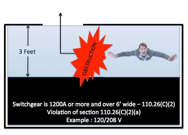
The general rule in section 110.26(C)(2) is that with respect to the aforementioned electrical equipment, one properly sized (24” or wider by 6.5’ or higher) entrance to and egress from opening at each end of the large electrical equipment. When this is not possible then the installer/designer has two options to the general rule. We will focus on option 110.26(C)(2)(a) in this part of the series.

110.26(C)(2)(a) - Unobstructed egress. For example, switchgear located in a room that offers proper working space clearances per section 110.26(A)(1) and provides no additional ability to maneuver around the working clearance space in the event of an electrical accident or hazardous occurrence where no adequate opening at each end of the equipment per the general rule is provided. The designer has created a serious unsafe condition to the future electrical worker.

Assuming you have the proper working space clearance in front of the electrical equipment and then another few feet to freely maneuver around the potential hazard without having to egress through the actual working space clearance then one unobstructed entrance to and egress from the working space may be acceptable. However, it is vital to understand that when using this option you can’t use the working space clearance as the egress path because it has the potential to be an obstruction in a potentially hazardous event, such as an electrical fire that could effectively block an electrical worker, inspector, engineer or visitor to one side of the electrical equipment. (See Images Below)


The reason the general rule requires properly sized entrances to and egress from both sides of the working space and electrical equipment as described earlier is to provide the electrical worker or other unfortunate individual two direct paths out of the potentially hazardous event area. The allowance for one entrance to and egress from the working space is when you can clearly step back out of the working space and then proceed unobstructed to the properly sized opening, while removing the unnecessary and potentially dangerous movement through the working space.


Need more evidence? Notice the second option 110.26(C)(2)(b), known as the double working clearance option, you double the working space clearance as expressed in 110.26(A)(1), you maintain no less than the prescribed working space clearance as defined in section 110.26(A)(1) from the nearest edge of the electrical equipment to the entrance. This double the working clearance and minimum clearance to the entrance from the electrical equipment provides the ability to step back into the “double” working space zone provided and effectively egress out the opening without having to traverse through the working space clearances as defined in section 110.26(A)(1).

In closing, It is my opinion that those who accept an installation that could place workers in danger and who knowingly permit improper application of the NEC rules may be found negligent in the event someone is trapped and ultimately harmed or killed in an electrical accident.


Best regards,

Paul W. Abernathy, CMI, CPI
Manager of Codes and Standards
Encore Wire

Friday, October 7, 2016

Tray Cable - Expanded Uses and Why Not! (Part 1)

Tray Cable - Part I

When the electrical industry thinks of tray cable they think industrial strength robust cable assembly designed to meet that tough rugged work environment. When I think of tray cable I see a simple nonmetallic-sheathed cable assembly that is constructed almost identically to service entrance cable with a much thicker nonmetallic jacket. I see inner electrical wires of the same type found in metal-clad cable, armored cable and the same as pulled in raceways on nearly every construction site in the country. So why is tray cable limited to specific uses in the National Electrical Code* if it's so similar to those other cable products. Well the answer is easier to find than you would ever have conceived.

Tray Cable is constructed under UL 1277. This UL-ANSI Standard is used by manufacturers to construct tray cable to specific cable construction specifications. The standard (UL 1277) also tells us the type of inner electrical wires that need to be used as well. Ironically those wires are exactly the same as the other cable assemblies, like Type MC, AC and SE Cables. So why limit tray cables use?.

The answer stems in the fact that tray cable itself directly competes with other products manufactured by companies who do not actually produce tray cable products.

We all know that service entrance cable is permitted to be installed in a wide variety of residential and commercial applications where deemed compliant with section 338.10 of the NEC*. The UL Standard for service entrance cable is UL 854. Ironically, the inner wires specified within service entrance cable are the same found in tray cable. However, with tray cable, the outer nonmetallic jacket is nearly double the thickness of any other nonmetallic cable jackets.

During the 2017 NEC Development Process the code making panel recognized that tray cable is just like any other nonmetallic cable assembly and should be treated as such. The code making panel expanded the use of tray cable in one and two family dwelling units for applications where the tray cable contains BOTH power and control conductors. While this author doesn't agree they went far enough in the expanded use of this product and some of the language was poorly written, like the term "both"which dramatically limits the expanded use which is likely the intended response. However, I am sure they might say the same thing about this article so i totally understand.

There are individuals who argue that tray cable is designed for industrial applications only. However, code making panel #7 disagrees with that logic. The code making panel summary agreed that tray cable is no different than any other nonmetallic cable. If the inner wires are the same THHN/THWN-2 or XHHW-2 wires that are used in service entrance cable, metal-clad cable, armored cable, and pulled in raceways then why treat is so differently. Is it possible that tray cable is a direct competitor to other wiring methods a company may already produce and could harm their bottom line?

So here is just one of my many arguments to expand the use of tray cable. As a master electrician in Virginia and electrical inspector for 30 years I have seen my share of installs where pulling service entrance cables over trusses and joists have ripped the nonmetallic jacket requiring corrective measures, with tray cable the jacket material is twice as thick in most cases and pulls easier without the fear of damage to the nonmetallic jacket.

In fact, on some construction job sites the extra robustness to the tray cable jacket itself may be something engineers and design professionals desire to specify in order to reduce potential damage to the nonmetallic jacket and ultimately the inner wires yet are handcuffed due to tray cables limitations currently within the NEC. Let's not forget that tray cable can be direct buried as well (where marked) while service entrance cables are not permitted for such an installation. Just imagine the possibilities.

This author has personally asked all the major manufacturers of tray cable what their concerns are for not expanding the use of tray cable in the same locations as service entrance cables and metal-clad cables are permitted. I have yet to get a legitimate response. Is it because tray cable is not required to pass a "joist pull test"? The 2017 NEC has established that within an informational note, unenforceable but does provide direction. However, it appears that UL has published a CRD on June 6, 2016 for tray cable manufacturers which added this test procedure to UL 1277. The test process is documented in the CRD and is aligned with those found in UL 719.

Let's also not forget that tray cable with the -ER designation has passed the same crush and impact tests as metal-clad cable, so why continue to limit it's expanded use? It is this authors opinion that section 336.10 needs a re-write to permit the expanded use of tray cable in all equivalent applications where other cable assemblies are already permitted.

There are some that will say tray cable is not tested to the standards of UL 854 so why compare it to service entrance cable, which could be conceived as a true statement. However, tray cable is tested to a higher crush and impact standard than service entrance cable, offers a much thicker nonmetallic jacket than service entrance cable yet both are permitted in cable trays per 392.10(A). Clearly tray cable can meet all the requirements within UL 854 and then some. In fact, tray cable passes all the joist pull testing requirements as specified in UL 854 for service entrance cables or UL 719 for nonmetallic-sheathed cables with flying colors.

We need to give electricians and design professionals more options which allows more robust nonmetallic cable assembly to be specified in applications where a more rugged cable assembly is needed. Tray cable is the perfect solution.

Remember, tray cable is constructed no differently than service entrance cable with the same inner wires and voltage ratings with the exception of the nonmetallic jacket, which is much thicker and more robust for that extra level of cable assembly protection.

By : Paul W. Abernathy,CMI

Manager of Codes and Standards

Encore Wire Corporation

* NEC or National Electrical Code are registered trademarks of the National Fire Protection Association. There use is for educational purposes only.

Wednesday, September 28, 2016

Sizing Circular Raceways for Multiconductor Cables - Made Easy


From time to time we get asked how to size a raceway where SE-R Cable is to be installed and how do we calculate the raceway fill requirements found in Chapter 9, Table 1 of the 2017 NEC*.

Determining the raceway fill for a complete raceway system (not for protection from physical damage) where Type SE-R Cable is to be installed is a simple calculation that often leaves electricians, engineers and inspectors confused. Again, keep in mind that this doesn't apply to short sections of raceway being used as physical protection for the SE-R Cable as denoted in Chapter 9, Table 1, Note 2 of the 2017 NEC.

All cable manufactures provide the diameter of their cables. This is usually found on their product information cut sheets. We will use our 4/0-4/0-4/0-2/0 AL SE-R from Encore Wire as an example for this article.

Since we are working with a cable assembly you need to determine what percentage of raceway fill the installer has to observe. Based on Chapter 9, Table 1, Note 9; a multiconductor cable of two or more conductors shall be treated as a single conductor for calculating percentage conduit fill area. Table 1 of Chapter 9 states that a single conductor (1) is to have a 53% maximum cross sectional area fill.

Once the fill percentage is established the user will draw their attention to the cable itself. In our published specifications reflects the diameter (straight across the cable from high point to high point) as 1.425 in. Based on the guidance provided in Chapter 9, Table 1, Note 9 of the 2017 NEC, the installer is going to use that diameter to perform a calculation nested within a normal mathematical formula.

Now, since we are looking for the area then we need to use that aforementioned formula to convert the diameter to an area. That formula can be done a few different ways. (𝝿/4) x D² is the base formula, in our case (𝝿/4) x 1.425² , which we added the diameter in place of the "D" in the formula. In complete value our formula is expressed as the following : 3.1415926536 ÷ 4 x 2.030625 = 1.5948491456 or simplified to 1.5948 which is now the approximate area for use with Chapter 9, Table 4.

As with any other raceway fill calculations, Table 4 comes into play. Once you have selected the raceway method you are installing, scroll over to the 53% fill column and find a raceway that will handle the 1.5948 in², which if the raceway was PVC Schedule 40 would result in a trade size 2 conduit. Again the benefit here is that the cable is considered a single conductor and can utilize the fill all the way to 53%.

Lastly, I also get questions on how to do this same calculation on a Type SE-U, NM-B, or UF-B cable and the calculation is just as simple. Chapter 9, Table 1, Note 9 also addresses "Elliptical" cross sectional areas as well. The NEC directs you to use the major diameter of the ellipse as a circle diameter just the same way we did for the previous Type SE-R example. The values for these types of cables are also found on the manufacturers product cut sheets or can be determined using a caliper tool where needed.

While this is not very complicated, it does generate many questions over the years on how to do the calculation, the hope is that this article will help eliminate the confusion on how to determine raceway fill for cables installed in circular raceways.

By Paul W Abernathy, CMI

Manager of Codes and Standards

All Rights Reserved- Copyright 2016

*NEC is a Registered trademark of the NFPA, National Fire Protection Association. We are not associated nor affiliated with NFPA.

Wednesday, March 9, 2016

Electrical Conductors, Electrical Wires and Electrical Cables - Explained

Electrical Conductors, Electrical Wires and Electrical Cables
 Over the past 30 years the term Conductors, Wires and Cables have been intertwined in a world of misunderstanding and potential misapplication. This article will attempt to bring clarity to these terms for everyday use in the electrical industry from a manufacturers perspective.
 The best way to begin to understand the differences is to attempt to define them in my own words.
 Electrical Cable(s) - Electrical cable(s) are an assembly consisting of one or more conductors with their own insulations, individual covering(s), and protective jacketing.
 Electrical Wire(s) - a thread or strand of copper or aluminum, typically manufactured from 5/16” or 3/8” solid copper or aluminum rods, then reduced down through a series of forming dies into specific standardized sizes and ultimately used as bare or insulated electrical conductors with thermoplastic, thermosetting or other listed insulating material along with additional coverings, where required by it’s associated UL Standard.
 Electrical Conductor(s) - an electrical conductor, of the wire type, is an electrical wire, available in solid or stranded design, and is produced to allow the flow of electrical current in one or more directions. A copper or aluminum bare or insulated electrical wire is a common electrical conductor of the wire type.
 While these definitions are my interpretation of their meanings, it is also important to understand that not all electrical conductors are actually of the wire type. There are other electrical conductors in the electrical industry that are not of the wire type yet considered to be electrical conductors. We are only focusing this article on the wire type of electrical conductor.
 When you examine the term electrical cable, the reader has to understand that cables can be of the single or multiple electrical wire type. The single electrical wires of a cable would have the same basic electrical cable elements as a multi-conductor cable, having a core electrical wire, typically with an insulating material prescribed by the governing standard to which it is being constructed and used as an electrical conductor, which is ultimately protected by an outer jacket or sheathing, where required by the UL Standard. The combination of these elements creates a single cable. In a multi-conductor cable you have multiple electrical wires, grouped or cabled together to form the core, which is ultimately jacketed in a protective sheathing to form a completed, and UL listed cable assembly.
 It is this author’s opinion that simply twisting or cabling electrical wires together doesn’t automatically create a cable assembly. Those would simply be electrical wires, being used as electrical conductors, which are simply twisted or cabled together to form the core design of an electrical cable assembly. All cable assemblies have to be listed by a Nationally Recognized Testing Laboratory (NRTL) and constructed in accordance with Underwriters Laboratory (UL) exacting standards. It is also important to understand that there are indeed cable assemblies that do not have an protective jacket yet are still UL listed for a specific application, for example, Deep Well Submersible Pump Cable which can come with or without a protective jacket or sheathing as long as it is listed and labeled for the specific application of use in accordance with UL. Simply twisting or cabling individual electrical wires would not by itself constitute a cable assembly unless it has been evaluated, listed and labeled as such.
 Now in support of this article we only need to examine the National Electrical Code [NEC] to see how the various terms are used. In Article 310, the code is clearly referencing conductors. The familiar conductor allowable ampacities, adjustments and corrections tables found in section 310.15 reference conductors and their association with how they are to be used. Chapter 3 of the code references the various acceptable wiring methods, which all of the cables associated are to be of the listed type.
 The transition from a manufactured electrical wire to what the NEC considered an electrical conductor, of the wire type, is theoretically being transformed within Article 310 of the NEC. The articles within chapter 3 begin to take those electrical conductors and utilize them into listed cable assembly types for use in the building wiring industry.
 Now, let’s look at the UL White Book, which I affectionately call the extended edition of the National Electrical Code. In examining the section titled “ Wire and Cable Markings”, the reader will quickly get an idea of what UL considered a wire versus a cable. Clearly electrical wires can be constructed into a cable assembly for ultimate listing and labeling but the difference is quite evident. In some cases like Type USE-2 cable, you indeed have individual electrical wires, now transformed into electrical conductors of the wire type, with or without a protective jacket or sheathing that have indeed been evaluated for use as a cable in or itself. However, what is clear is that you simply do not call an XHHW-2 or a THHN/THWN-2 a cable when it is indeed within the eyes of UL and the NEC an electrical conductor of the wire type, which was transformed from being manufactured as simply an electrical wire.
 Lastly, while I do not put a lot of assurance in “Google” searches, and the results below confirm this position, I did a search on the following phrase “ What is the difference between a wire and a cable” and the search results are interesting, which as expected I do not 100% agree with:
 “A wire is a single conductor (material most commonly being copper or aluminum) while cable is two or more insulated wires wrapped in one jacket.”
 As we have seen it doesn’t technically take two or more insulated electrical wires or electrical conductors of the wire type to be considered a cable, and clearly in many cases the protective jacket or sheathing is optional. What is clear is that all cables have to be listed and labeled for their specific use and taking individually UL Listed electrical wires or electrical conductors of the wire type and twisting them together do not guarantee they are to be considered a cable assembly.
 As opinions will vary, the goal here was to attempt to simplify the basic understanding of the differences in electrical conductors, electrical wires and electrical cables and I hope we have succeeded in that effort.
Paul W Abernathy, CMI
Manager of Codes and Standards
Encore Wire Corporation
 References: 2014 UL White Book - Guide Information For Electrical Equipment
                       2014 National Electrical Code (NEC-NFPA70)
 NEC and the National Electrical Code are registered trademarks of the National Fire Protection Association and in no way endorse my opinions within this article.
UL is a registered trademark of Underwriters Laboratory and in no way endorse my opinions within this article.