Friday, December 30, 2016

Entrance to and Egress from Working Spaces - Single Entrance Option 110.26(C)(2)(a)

Greetings Mr. Design Engineer,

Thank you for submitting your question with regards to the proper application of section 110.26(C)(2)(a) as it pertains to establishing a compliant and safe single entrance to and egress from large electrical equipment rated 1200 amps or more and over 6 feet wide that contain overcurrent devices, or control devices, or switching devices.

The general rule in section 110.26(C)(2) is that with respect to the aforementioned electrical equipment, one properly sized (24” or wider by 6.5’ or higher) entrance to and egress from opening at each end of the large electrical equipment. When this is not possible then the installer/designer has two options to the general rule. We will focus on option 110.26(C)(2)(a) in this part of the series.

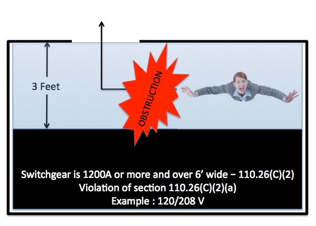
110.26(C)(2)(a) - Unobstructed egress. For example, switchgear located in a room that offers proper working space clearances per section 110.26(A)(1) and provides no additional ability to maneuver around the working clearance space in the event of an electrical accident or hazardous occurrence where no adequate opening at each end of the equipment per the general rule is provided. The designer has created a serious unsafe condition to the future electrical worker.

Assuming you have the proper working space clearance in front of the electrical equipment and then another few feet to freely maneuver around the potential hazard without having to egress through the actual working space clearance then one unobstructed entrance to and egress from the working space may be acceptable. However, it is vital to understand that when using this option you can’t use the working space clearance as the egress path because it has the potential to be an obstruction in a potentially hazardous event, such as an electrical fire that could effectively block an electrical worker, inspector, engineer or visitor to one side of the electrical equipment. (See Images Below)


The reason the general rule requires properly sized entrances to and egress from both sides of the working space and electrical equipment as described earlier is to provide the electrical worker or other unfortunate individual two direct paths out of the potentially hazardous event area. The allowance for one entrance to and egress from the working space is when you can clearly step back out of the working space and then proceed unobstructed to the properly sized opening, while removing the unnecessary and potentially dangerous movement through the working space.


Need more evidence? Notice the second option 110.26(C)(2)(b), known as the double working clearance option, you double the working space clearance as expressed in 110.26(A)(1), you maintain no less than the prescribed working space clearance as defined in section 110.26(A)(1) from the nearest edge of the electrical equipment to the entrance. This double the working clearance and minimum clearance to the entrance from the electrical equipment provides the ability to step back into the “double” working space zone provided and effectively egress out the opening without having to traverse through the working space clearances as defined in section 110.26(A)(1).

In closing, It is my opinion that those who accept an installation that could place workers in danger and who knowingly permit improper application of the NEC rules may be found negligent in the event someone is trapped and ultimately harmed or killed in an electrical accident.


Best regards,

Paul W. Abernathy, CMI, CPI
Manager of Codes and Standards
Encore Wire

Friday, October 7, 2016

Tray Cable - Expanded Uses and Why Not! (Part 1)

Tray Cable - Part I

When the electrical industry thinks of tray cable they think industrial strength robust cable assembly designed to meet that tough rugged work environment. When I think of tray cable I see a simple nonmetallic-sheathed cable assembly that is constructed almost identically to service entrance cable with a much thicker nonmetallic jacket. I see inner electrical wires of the same type found in metal-clad cable, armored cable and the same as pulled in raceways on nearly every construction site in the country. So why is tray cable limited to specific uses in the National Electrical Code* if it's so similar to those other cable products. Well the answer is easier to find than you would ever have conceived.

Tray Cable is constructed under UL 1277. This UL-ANSI Standard is used by manufacturers to construct tray cable to specific cable construction specifications. The standard (UL 1277) also tells us the type of inner electrical wires that need to be used as well. Ironically those wires are exactly the same as the other cable assemblies, like Type MC, AC and SE Cables. So why limit tray cables use?.

The answer stems in the fact that tray cable itself directly competes with other products manufactured by companies who do not actually produce tray cable products.

We all know that service entrance cable is permitted to be installed in a wide variety of residential and commercial applications where deemed compliant with section 338.10 of the NEC*. The UL Standard for service entrance cable is UL 854. Ironically, the inner wires specified within service entrance cable are the same found in tray cable. However, with tray cable, the outer nonmetallic jacket is nearly double the thickness of any other nonmetallic cable jackets.

During the 2017 NEC Development Process the code making panel recognized that tray cable is just like any other nonmetallic cable assembly and should be treated as such. The code making panel expanded the use of tray cable in one and two family dwelling units for applications where the tray cable contains BOTH power and control conductors. While this author doesn't agree they went far enough in the expanded use of this product and some of the language was poorly written, like the term "both"which dramatically limits the expanded use which is likely the intended response. However, I am sure they might say the same thing about this article so i totally understand.

There are individuals who argue that tray cable is designed for industrial applications only. However, code making panel #7 disagrees with that logic. The code making panel summary agreed that tray cable is no different than any other nonmetallic cable. If the inner wires are the same THHN/THWN-2 or XHHW-2 wires that are used in service entrance cable, metal-clad cable, armored cable, and pulled in raceways then why treat is so differently. Is it possible that tray cable is a direct competitor to other wiring methods a company may already produce and could harm their bottom line?

So here is just one of my many arguments to expand the use of tray cable. As a master electrician in Virginia and electrical inspector for 30 years I have seen my share of installs where pulling service entrance cables over trusses and joists have ripped the nonmetallic jacket requiring corrective measures, with tray cable the jacket material is twice as thick in most cases and pulls easier without the fear of damage to the nonmetallic jacket.

In fact, on some construction job sites the extra robustness to the tray cable jacket itself may be something engineers and design professionals desire to specify in order to reduce potential damage to the nonmetallic jacket and ultimately the inner wires yet are handcuffed due to tray cables limitations currently within the NEC. Let's not forget that tray cable can be direct buried as well (where marked) while service entrance cables are not permitted for such an installation. Just imagine the possibilities.

This author has personally asked all the major manufacturers of tray cable what their concerns are for not expanding the use of tray cable in the same locations as service entrance cables and metal-clad cables are permitted. I have yet to get a legitimate response. Is it because tray cable is not required to pass a "joist pull test"? The 2017 NEC has established that within an informational note, unenforceable but does provide direction. However, it appears that UL has published a CRD on June 6, 2016 for tray cable manufacturers which added this test procedure to UL 1277. The test process is documented in the CRD and is aligned with those found in UL 719.

Let's also not forget that tray cable with the -ER designation has passed the same crush and impact tests as metal-clad cable, so why continue to limit it's expanded use? It is this authors opinion that section 336.10 needs a re-write to permit the expanded use of tray cable in all equivalent applications where other cable assemblies are already permitted.

There are some that will say tray cable is not tested to the standards of UL 854 so why compare it to service entrance cable, which could be conceived as a true statement. However, tray cable is tested to a higher crush and impact standard than service entrance cable, offers a much thicker nonmetallic jacket than service entrance cable yet both are permitted in cable trays per 392.10(A). Clearly tray cable can meet all the requirements within UL 854 and then some. In fact, tray cable passes all the joist pull testing requirements as specified in UL 854 for service entrance cables or UL 719 for nonmetallic-sheathed cables with flying colors.

We need to give electricians and design professionals more options which allows more robust nonmetallic cable assembly to be specified in applications where a more rugged cable assembly is needed. Tray cable is the perfect solution.

Remember, tray cable is constructed no differently than service entrance cable with the same inner wires and voltage ratings with the exception of the nonmetallic jacket, which is much thicker and more robust for that extra level of cable assembly protection.

By : Paul W. Abernathy,CMI

Manager of Codes and Standards

Encore Wire Corporation

* NEC or National Electrical Code are registered trademarks of the National Fire Protection Association. There use is for educational purposes only.

Wednesday, September 28, 2016

Sizing Circular Raceways for Multiconductor Cables - Made Easy


From time to time we get asked how to size a raceway where SE-R Cable is to be installed and how do we calculate the raceway fill requirements found in Chapter 9, Table 1 of the 2017 NEC*.

Determining the raceway fill for a complete raceway system (not for protection from physical damage) where Type SE-R Cable is to be installed is a simple calculation that often leaves electricians, engineers and inspectors confused. Again, keep in mind that this doesn't apply to short sections of raceway being used as physical protection for the SE-R Cable as denoted in Chapter 9, Table 1, Note 2 of the 2017 NEC.

All cable manufactures provide the diameter of their cables. This is usually found on their product information cut sheets. We will use our 4/0-4/0-4/0-2/0 AL SE-R from Encore Wire as an example for this article.

Since we are working with a cable assembly you need to determine what percentage of raceway fill the installer has to observe. Based on Chapter 9, Table 1, Note 9; a multiconductor cable of two or more conductors shall be treated as a single conductor for calculating percentage conduit fill area. Table 1 of Chapter 9 states that a single conductor (1) is to have a 53% maximum cross sectional area fill.

Once the fill percentage is established the user will draw their attention to the cable itself. In our published specifications reflects the diameter (straight across the cable from high point to high point) as 1.425 in. Based on the guidance provided in Chapter 9, Table 1, Note 9 of the 2017 NEC, the installer is going to use that diameter to perform a calculation nested within a normal mathematical formula.

Now, since we are looking for the area then we need to use that aforementioned formula to convert the diameter to an area. That formula can be done a few different ways. (𝝿/4) x D² is the base formula, in our case (𝝿/4) x 1.425² , which we added the diameter in place of the "D" in the formula. In complete value our formula is expressed as the following : 3.1415926536 ÷ 4 x 2.030625 = 1.5948491456 or simplified to 1.5948 which is now the approximate area for use with Chapter 9, Table 4.

As with any other raceway fill calculations, Table 4 comes into play. Once you have selected the raceway method you are installing, scroll over to the 53% fill column and find a raceway that will handle the 1.5948 in², which if the raceway was PVC Schedule 40 would result in a trade size 2 conduit. Again the benefit here is that the cable is considered a single conductor and can utilize the fill all the way to 53%.

Lastly, I also get questions on how to do this same calculation on a Type SE-U, NM-B, or UF-B cable and the calculation is just as simple. Chapter 9, Table 1, Note 9 also addresses "Elliptical" cross sectional areas as well. The NEC directs you to use the major diameter of the ellipse as a circle diameter just the same way we did for the previous Type SE-R example. The values for these types of cables are also found on the manufacturers product cut sheets or can be determined using a caliper tool where needed.

While this is not very complicated, it does generate many questions over the years on how to do the calculation, the hope is that this article will help eliminate the confusion on how to determine raceway fill for cables installed in circular raceways.

By Paul W Abernathy, CMI

Manager of Codes and Standards

All Rights Reserved- Copyright 2016

*NEC is a Registered trademark of the NFPA, National Fire Protection Association. We are not associated nor affiliated with NFPA.

Wednesday, March 9, 2016

Electrical Conductors, Electrical Wires and Electrical Cables - Explained

Electrical Conductors, Electrical Wires and Electrical Cables
 Over the past 30 years the term Conductors, Wires and Cables have been intertwined in a world of misunderstanding and potential misapplication. This article will attempt to bring clarity to these terms for everyday use in the electrical industry from a manufacturers perspective.
 The best way to begin to understand the differences is to attempt to define them in my own words.
 Electrical Cable(s) - Electrical cable(s) are an assembly consisting of one or more conductors with their own insulations, individual covering(s), and protective jacketing.
 Electrical Wire(s) - a thread or strand of copper or aluminum, typically manufactured from 5/16” or 3/8” solid copper or aluminum rods, then reduced down through a series of forming dies into specific standardized sizes and ultimately used as bare or insulated electrical conductors with thermoplastic, thermosetting or other listed insulating material along with additional coverings, where required by it’s associated UL Standard.
 Electrical Conductor(s) - an electrical conductor, of the wire type, is an electrical wire, available in solid or stranded design, and is produced to allow the flow of electrical current in one or more directions. A copper or aluminum bare or insulated electrical wire is a common electrical conductor of the wire type.
 While these definitions are my interpretation of their meanings, it is also important to understand that not all electrical conductors are actually of the wire type. There are other electrical conductors in the electrical industry that are not of the wire type yet considered to be electrical conductors. We are only focusing this article on the wire type of electrical conductor.
 When you examine the term electrical cable, the reader has to understand that cables can be of the single or multiple electrical wire type. The single electrical wires of a cable would have the same basic electrical cable elements as a multi-conductor cable, having a core electrical wire, typically with an insulating material prescribed by the governing standard to which it is being constructed and used as an electrical conductor, which is ultimately protected by an outer jacket or sheathing, where required by the UL Standard. The combination of these elements creates a single cable. In a multi-conductor cable you have multiple electrical wires, grouped or cabled together to form the core, which is ultimately jacketed in a protective sheathing to form a completed, and UL listed cable assembly.
 It is this author’s opinion that simply twisting or cabling electrical wires together doesn’t automatically create a cable assembly. Those would simply be electrical wires, being used as electrical conductors, which are simply twisted or cabled together to form the core design of an electrical cable assembly. All cable assemblies have to be listed by a Nationally Recognized Testing Laboratory (NRTL) and constructed in accordance with Underwriters Laboratory (UL) exacting standards. It is also important to understand that there are indeed cable assemblies that do not have an protective jacket yet are still UL listed for a specific application, for example, Deep Well Submersible Pump Cable which can come with or without a protective jacket or sheathing as long as it is listed and labeled for the specific application of use in accordance with UL. Simply twisting or cabling individual electrical wires would not by itself constitute a cable assembly unless it has been evaluated, listed and labeled as such.
 Now in support of this article we only need to examine the National Electrical Code [NEC] to see how the various terms are used. In Article 310, the code is clearly referencing conductors. The familiar conductor allowable ampacities, adjustments and corrections tables found in section 310.15 reference conductors and their association with how they are to be used. Chapter 3 of the code references the various acceptable wiring methods, which all of the cables associated are to be of the listed type.
 The transition from a manufactured electrical wire to what the NEC considered an electrical conductor, of the wire type, is theoretically being transformed within Article 310 of the NEC. The articles within chapter 3 begin to take those electrical conductors and utilize them into listed cable assembly types for use in the building wiring industry.
 Now, let’s look at the UL White Book, which I affectionately call the extended edition of the National Electrical Code. In examining the section titled “ Wire and Cable Markings”, the reader will quickly get an idea of what UL considered a wire versus a cable. Clearly electrical wires can be constructed into a cable assembly for ultimate listing and labeling but the difference is quite evident. In some cases like Type USE-2 cable, you indeed have individual electrical wires, now transformed into electrical conductors of the wire type, with or without a protective jacket or sheathing that have indeed been evaluated for use as a cable in or itself. However, what is clear is that you simply do not call an XHHW-2 or a THHN/THWN-2 a cable when it is indeed within the eyes of UL and the NEC an electrical conductor of the wire type, which was transformed from being manufactured as simply an electrical wire.
 Lastly, while I do not put a lot of assurance in “Google” searches, and the results below confirm this position, I did a search on the following phrase “ What is the difference between a wire and a cable” and the search results are interesting, which as expected I do not 100% agree with:
 “A wire is a single conductor (material most commonly being copper or aluminum) while cable is two or more insulated wires wrapped in one jacket.”
 As we have seen it doesn’t technically take two or more insulated electrical wires or electrical conductors of the wire type to be considered a cable, and clearly in many cases the protective jacket or sheathing is optional. What is clear is that all cables have to be listed and labeled for their specific use and taking individually UL Listed electrical wires or electrical conductors of the wire type and twisting them together do not guarantee they are to be considered a cable assembly.
 As opinions will vary, the goal here was to attempt to simplify the basic understanding of the differences in electrical conductors, electrical wires and electrical cables and I hope we have succeeded in that effort.
Paul W Abernathy, CMI
Manager of Codes and Standards
Encore Wire Corporation
 References: 2014 UL White Book - Guide Information For Electrical Equipment
                       2014 National Electrical Code (NEC-NFPA70)
 NEC and the National Electrical Code are registered trademarks of the National Fire Protection Association and in no way endorse my opinions within this article.
UL is a registered trademark of Underwriters Laboratory and in no way endorse my opinions within this article.

Monday, February 22, 2016


New Video Release - From the Desk of Codes and Standards (Tray Cable 101)

Join Encore Wire's Manager of Codes and Standards as he explains the construction and uses of Type TC Cable and answered a few questions on it's use. Join Paul as he gives you a better understanding of Type TC (Tray Cable) from a manufacturers perspective.


New Video Release - From the Desk of Codes and Standards (Type MC-LED)

Join Encore Wire's Manager of Codes and Standards as he explains the construction and uses of Type MC-LED and answered a few questions on it's use. This episode explains the misconception about the use of Type MC-LED in environmental air spaces (plenum) and for uses other than just for lighting systems.


Wired for Healthcare...

Just What the Doctor Ordered.

McKinney, TX., January 1, 2016 – Encore Wire introduced to their manufacturer representatives their newest addition in the existing Type MC-LED (Type PCS) product line, MC-LED HealthcareTM, the next generation of Encore’s hybrid power and control/signal conductor cable system. MC-LED Healthcare incorporates Encore’s advanced SmartGroundTM technology, which provides the required redundant grounding path demanded by Section 517.13(a) of the National Electrical Code® for use in patient care areas of hospitals, nursing homes, dental offices, outpatient and other types of healthcare facilities.

"As emerging energy saving technology rapidly expands in the 21st century, so should the cabling technology that powers the world's energy conservation. Encore Wire’s Type MC-LED Healthcare cable was specifically designed to adapt and overcome existing cable limitations with proven innovative solutions.”- Paul Abernathy, Encore Wire Codes & Standards Manager.

MC-LED Healthcare is ideal for use in 0-10V dimming control and energy management systems in health care facilities where energy management is critical to effective and sustainable operations. Encore’s specialized redundant grounding system features a bare aluminum bonding/grounding conductor installed in intimate contact with all convolutions within the armored cable system, which ensures a more effective and reliable grounding system in health care environments where grounding and bonding redundancy is critical to environmental safety. MC-LED Healthcare is available with 12 AWG or 10 AWG CU Type THHN/THWN-2 power conductors, along with an individually twisted and jacketed pair of 16 AWG CU Type TFN or equivalent conductors.

For more information about Encore Wire's MC-LED Healthcare, please contact Kyle Carter at 972.562.9473 ext. 277 or visit encorewire.com. For our Codes & Standards video, go to youtube.com.

About Encore Wire
Encore Wire Corporation is a leading manufacturer of a broad range of electrical building wire for interior wiring in commercial and industrial buildings, homes, apartments, and manufactured housing. The Company is focused on maintaining a high level of customer service with low-cost production and the addition of new products that complement its current product line. To learn more about Encore Wire, its products and culture, visit encorewire.com, YouTube, and Facebook.


Encore Wire Corporation
1329 Millwood Road
McKinney, TX 75069
972.562.9473
www.encorewire.com

Media Contact:
Karolina Zuraw
Marketing Manager
karolina.zuraw@encorewire.com
972.562.9473 Ext. 210